
Преобразователь частоты Altivar Machine ATV320 4 КВТ 500В 3Ф


- В наличии
- Код: ATV320U40N4C
29 377,19 ₴
23 501,75 ₴
- +380 (68) 052-00-91viber Для замовлень Viber

Преобразователи частоты серии Altivar Machine ATV320 предназначены для регулируемых по скорости приводов с трехфазными синхронными и асинхронных двигателями, содержащими прикладные функции, актуальные для самого широкого круга применений.
Основные технические характеристики преобразователей частоты ATV320:
![]() Надежное управление асинхронными или синхронными двигателями
Надежное управление асинхронными или синхронными двигателями
![]() Полноценная интеграция в коммуникационную систему любой архитектуры
Полноценная интеграция в коммуникационную систему любой архитектуры
![]() Компактное или «книжное» исполнение для встраивания во все типы шкафов
Компактное или «книжное» исполнение для встраивания во все типы шкафов
![]() Встроенные функции безопасности
Встроенные функции безопасности
![]() Увеличенная устойчивость к агрессивным средам
Увеличенная устойчивость к агрессивным средам
|
|||||||||||||||||||||||||||||||||||||||||||||||||||||||
Заказчики также покупают эти Функции коммуникации
Цена 690,37 UAH
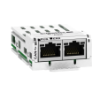
Коммуникационная карта - последовательное подключение по шине CANopen, 2 x RJ45
Цена 1 641,70 UAH

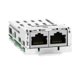
Коммуникационная карта Ethernet ATV32 LXM32
Цена 2 033,15 UAH
Коммуникационная карта Profinet
Цена 3 831,77 UAH
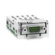
Коммуникационная карта CANopen SUB-D9
Цена 1 716,94 UAH
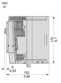
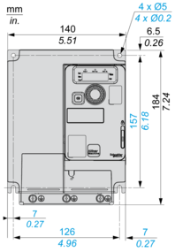
Dimensions Drawings
Dimensions
Right View, Front View and Front View with EMC Plate

Mounting and Clearance
Mounting Types
Mounting Type A: Individual with Ventilation Cover

Only Possible at Ambient Temperature Less or Equal to 50 °C (122 °F)
Mounting Type B: Side by Side, Ventilation Cover Removed

Mounting Type C: Individual, Ventilation Cover Removed

For Operation at Ambient Temperature Above 50 °C (122 °F)
Connections and Schema
Connection Diagrams
Diagram with Line Contactor
Connection diagrams conforming to standards ISO13849 category 1 and IEC/EN 61508 capacity SIL1, stopping category 0 in accordance with standard IEC/EN 60204-1.

(1) Line choke (if used)
(2) Fault relay contacts, for remote signaling of drive status
Diagram with Switch Disconnect
Connection diagrams conforming to standards EN 954-1 category 1 and IEC/EN 61508 capacity SIL1, stopping category 0 in accordance with standard IEC/EN 60204-1.

(1) Line choke (if used)
(2) Fault relay contacts, for remote signaling of drive status
Control Connection Diagram in Source Mode
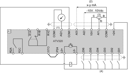
(1) Analog output
(2) Analog inputs
(3) Reference potentiometer (10 kOhm maxi)
(4) Digital inputs
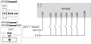
Digital Inputs Wiring
The logic input switch (SW1) is used to adapt the operation of the logic inputs to the technology of the programmable controller outputs.
Switch SW1 set to “Source” position and use of the output power supply for the DIs.
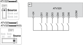
Switch SW1 set to “Source” position and use of an external power supply for the DIs.

Switch SW1 set to “Sink Int” position and use of the output power supply for the DIs.

Switch SW1 set to “Sink Ext” position and use of an external power supply for the DIs.
| Основные атрибуты | |
|---|---|
| Производитель | Schneider Electric |
| Страна производитель | Франция |
| Количество фаз | 3 |
| Максимальный ток | 9.5 А |
| Мощность | 4 кВт |
| Тип рабочей величины | Мощность |
- Цена: 23 501,75 ₴
